This is my water proof Pick and place robot which has a custom designed convener belt, servo based arm, light weighted, heavy lift capability, long time battery backup(LIPO battery is used), and a water pump
This is a simple magnetic levitator which suspends objects a set distance below an electromagnet. The physics behind it is to simply provide a magnetic force which equal and opposite to the gravitational force on the object. The two forces cancel and the object remains suspended. Practically this is done by a circuit which reduces electromagnet force when an object gets to close, and increases it when the object is out of range.
This circuit works by comparing the signals from the sensors with the first op-amp and sending out a voltage proportional to the difference or "error". The error signal is then sent through a compensation network which acts a high-pass filter, allowing quick changes in error to pass easier than slow changes. This is required to stabilize the control loop, and without it objects would just flutter close to the electromagnet due to the system being unstable. The signal is then amplified to it's original amplitude, since the compensation network attenuated it, and finally drives the TIP122 Darlington transistor, which controls the electromagnet current. The extra diodes around the transistor are to prevent damage to the transistor. The signal diode on the base prevents reverse biasing the base, which is damaging, while the two 1N4001's give a path for the magnetizing current to flow when the electromagnet turns off. The optical components used aren't too critical, as long as their wavelengths match up ok, and the detection/emission angles aren't too narrow. The IR LEDs are TIL38, which are 940nm peak, have 15 degree spread, 35mW and 100mA max. The detectors are PT204-6B, which are IR phototransistors.
Construction Details
The top detector is a reference detector and the bottom one senses when an object is in levitating position. The object detector must be level with the IR LED. The reference detector must see the IR diode at all times, even when levitating an object. The electromagnet should have maximum 15 ohms of resistance, any more and it will not be able to lift anything. Too little resistance and the transistor will have problems regulating electromagnet current and will also dissipate more heat. When constructing an electromagnet there are two things to remember. Magnetic force is proportional to the number of turns and current. So when using copper wire the magnetic force is roughly proportional to the square of the power dissipated in it, for all practical use. In my coil I used 70 meters of 0.45mm magnet wire. The coil can be wound on almost any ferrous metal rod if you're not concerned with efficiency. Remember that keeping the surface area of the face small will keep the object centered better. Constructing the circuit correctly is easiest if built in two parts; part 1 with the detectors and first op-amp to make sure the output swings when an object is put in the beam, and then part 2 with the rest. This way it will be much easier to troubleshoot.
Troubleshooting
If the levitator fails to suspend anything, but objects “flutter”, you will need to adjust the compensation network. Try changing resistor values and capacitor values. The compensation network is the 150K, 1K resistor and 100nF cap between op-amp1 and 2. Decreasing the value of the 150K and/or increasing the value of the 1K will often solve the fluttering problems. Sometimes fluttering problems are caused by the reference detector not being setup properly. If the coil doesn’t turn off even when an object is put in the beam, check the reference and object detectors.
Controlling LED's by wireless KEYBOARD(Serial communication between ARDUINO and KEYBOARD)
Author:- M.Sundeep Goud (sundeep.2488@gmail.com)
Controlling a bunch of LED's by using ARDUINO In this project i made Serial communication between ARDUINO and Wireless KEYBOARD
keys Function:-
0 It make's all LED's to OFF at a time 1 It make's all LED's to ON at time 2 It make's all LED's to ON and OFF continuously taking some time interval(delay) 3 It make's LED's to ON and OFF Randomly taking some time between each LED(i.e t=100 msec delay) 4 It make's LED's to ON and OFF Randomly taking some time between each LED(i.e t=50 msec delay) 5 It make's LED's to ON and OFF Randomly taking some time between each LED(i.e t=10 msec delay)
In this project i am controlling a bunch of LED's with wireless Keyboard by using ARDUINO and PC. To make communication with PC and ARDUINO i am using Serial port(TX, RX, VCC, GND)
so that i can pass commands to my ARDUINO and control LED's
Serial communication Used for communication between the Arduino board and a computer or other devices. All Arduino boards have at least one serial port (also known as a UART or USART): Serial. It communicates on digital pins 0 (RX) and 1 (TX) as well as with the computer via USB. Thus, if you use these functions, you cannot also use pins 0 and 1 for digital input or output.
You can use the Arduino environment's built-in serial monitor to communicate with an Arduino board. Click the serial monitor button in the toolbar and select the same baud rate used in the call to begin().
The project is to control the sound in speaker by varying frequency. In this project i used LDR, LED, speaker and ARDUINO to control the frequency. as u can see in the above video the tone(frequency) of speaker varies as the position of my finger moves between LDR and LED
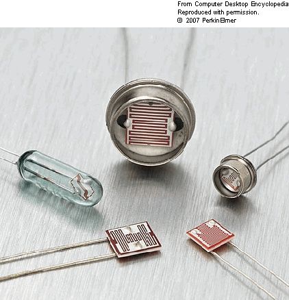
LDR (Light Dependent Resistor)
A light-dependent resistor, alternatively called an LDR, photoresistor,photoconductor, or photocell, is a variable resistor whose value decreases with increasing incident light intensity.
An LDR is made of a high-resistance semiconductor. If light falling on the device is of high enough frequency, photons absorbed by the semiconductor give bound electrons enough energy to jump into the conduction band. The resulting free electron (and its hole partner) conduct electricity, thereby lowering resistance.
A photoelectric device can be either intrinsic or extrinsic. In intrinsic devices, the only available electrons are in the valence band, and hence the photon must have enough energy to excite the electron across the entire bandgap. Extrinsic devices have impurities added, which have a ground state energy closer to the conduction band - since the electrons don't have as far to jump, lower energy photons (i.e. longer wavelengths and lower frequencies) are sufficient to trigger the device.
ARDUINO
The Arduino Uno is a microcontroller board based on the ATmega328 (datasheet). It has 14 digital input/output pins (of which 6 can be used as PWM outputs), 6 analog inputs, a 16 MHz ceramic resonator, a USB connection, a power jack, an ICSP header, and a reset button. It contains everything needed to support the microcontroller; simply connect it to a computer with a USB cable or power it with a AC-to-DC adapter or battery to get started.
IR Reactive LED's using ARDUINO microcontroller.(controlling single LED)
IR Reactive LED's using ATMEGA16A microcontroller(controlling bunch of LED) Hardware used:-
LED's
IR pare (TX, RX)
ATMEGA16A
Resisters(220E)
Regulator(7805)
Power Source
Plank
This is the project completely based on IR rays manipulation. As we can see there are bunch of LED's (IR and Ultra-while) placed regular fashion on the plank and this LED's are activated if and only any abstract passes over it. When abstract is placed on the plank with certain distance the IR rays emitted by IR emitter get Reflected by the abstract and this Reflected rays are detected by IR receiver and this whole process is monitored by a microcontroller (ATMEGA16A). As soon as the IR RX detects the reflected rays it will give analog information to my microcontroller. Now microcontroller converts the analog data to digital(ADC) and controlles the LED's with respective to the data. In this way the LED's are going to be controlled
Patterns Display using POV (Persistence of Vision)
Author:- M.Sundeep Goud( sundeep.2488@gmail.com )
The project mainly works with the principal of POV(persistence of vision). Persistence of vision is the phenomenon of the eye by which an afterimage is thought to persist for approximately one twenty-fifth of a second on the retina.[citation needed]The myth of persistence of vision is the belief that human perception of motion (brain centered) is the result of persistence of vision (eye centered). The myth was debunked in 1912 by Wertheimer[1] but persists in many citations in many classic and modern film-theory texts.A more plausible theory to explain motion perception (at least on a descriptive level) are two distinct perceptual illusions: phi phenomenon and beta movement.
In this project i am going to control 24 LED's with the help of ATMEG16A Microcontroller. The LED's are arranged in a single Row on a rectangular PCB. this LED's +ve terminals are directly connected to I/O ports of ATMEGA16A and -ve ends are connected to 220 ohms resister then it is grounded. Resisters are used to control the flow of current in LED's.
The whole setup was connected on a 1000 RPM DC motor so that the LED's start rotating and forms Patterns as we can see in the above viedo
Wireless Sensor Network Based Home Monitoring System
Author:- M.Sundeep Goud( sundeep.2488@gmail.com )
Besoin for Home Monitoring & Security System:
Wireless-sensor-network-based home monitoring & security system involves function assessment of daily activities. As the science and technology has been rapidly growing now a days, the standard of living of the people has been increased. The rich people can afford to automation of their houses by using the modern technology by spending heavy expenditure on it .Here we are discussing about a home monitoring & security system which is self-controlled. Controlling is achieved by using a RF remote and a mobile phone which can be afforded by a poor man. This project main aim is to provide advanced home based controllers for poor people in less cost so that poor people can also take complete advantage of advanced technology and lead their life in very comfort way. Not only for poor people it also helps senior citizen by reducing day to day work like on/off switching, locking door, monitoring water level in tank.
Abstract:
Wireless sensor network based home monitoring & security system involves functional assessment of daily activities like locking and unlocking of door and controlling the house hold appliances. In this project we reported a mechanism for controlling the condition of house hold appliances connected through various sensor units. We defined, new functions to determine the status of the door means locking or unlocking and controlling the switches of house hold appliances. The monitoring & security system of essential activities are developed, evaluated & tested at home & attained best results.
Objectives:
1. Locking and Unlocking a door by using LABVIEW and GPRS/GSM mobile phones (Authorized Subscriber Identity Module (SIM) with no charges).
2.Controlling switches by using a RF remote and specially designed system application i.e. LABVIEW & SMART PHONE.
3.Regulating ceiling fan by using RF remote.
4.24 hours Complete security with siren and call (independent of power at home).
5.Water tank level indicator.
6.Fire accidents controllers with siren and call.
7.In case of House Break the owner receives a call and the camera captures the images and saves them in SD card.
8. In case the thieves are entered the home weapon module get activated & hits the target (thief) & makes him unconscious for a period of time.
Description:
This is the Front panel of Labview
The circular LEDs represents each switch in the switch board module. Switch are represented with a DARK GREEN buttons(shown above),they turns into LIGHT GREEN when it is selected .As soon as the switch is selected on labview the respective switch on switch board module is activated and same switch on labview is used to deactivate. We can also control door by using labview with a switch located at the right side(vertical),which is used to access the door. By hitting the same switch we can lock and unlock the door.These home appliances can also be controlled by a smart phone by using TEAMVIEWER software,this software allows the smart phone to control system.
Project is divided into 6 different modules.
Module-1 (Master):
It consists of 2 ATMEGA16A controller with Dot Matrix display, 4*4 keypad (Calculator), PIR sensor (for security), temperature sensor (IN CASE OF ABNORMAL TEMP) &LCD display. Interfaced with mobile consisting of camera for capturing the Images of House breakers (thieves) & callback to house owner .It is used as calculator, We can control home appliances and door with Laptop or Desktop by Interfacing with Master module. Master module got PIR sensor in it which helps to monitor the home in the absence of owners. In the case of emergency(Fire accidents, homebreak) master module will call the owner and starts taking snapshots continuously with the the help of mobile connected in it.
Module-2 (Remote RF Tx) :
It consists of ATMEGA8A controller with 18 keys to access the switch board, speaker & torch. This module will help us to control home appliances.By pressing specified key its corresponding switch gets activated. Operating remote is as simple as operating normal Tv Remote including additional feature like Torch light. It has a range of 500 ft (as per the datasheet of RF module 434 mhz) ands signals can penetrate through the obstacles (walls, doors, human body, etc...).
Module-3 (Switch Board RF Rx) :
It consists of ATMEGA16A controller with 24 pair of terminals (OPTOCOUPLER's & TRAIC's), buzzer (for water level indicator). It can control up to 12 AMPERES RMS 600 thru 800 VOLTS. This module can be controlled using PC(with labview), Smart mobiles, Remote module.Module should be installed back of the commonly used Switch boards. Switch Board Module has 24 pair of terminals to which 24 different home appliances are connected and voltage can also varied using remote. It also includes Water level Indicator i.e Buzzer. and
FUSE which prevents home appliances from high currents.
Moodule-4 (Door RF Rx) :
It consists of ATMEGA8A controller, motor driver (to lock & unlock the door), buzzer (to indicate whether the door is in engage ) & LEDS (RED-LOCK, GREEN-UNLOCK). By installing this module to our door,one can access the door by using PC, Smart Phone, Manually by sitting at any corner of the world. These doors are only accessed(locked and unlocked) by authorized persons and authorized phones.
Module-5 (Siren) :
It consists of ATTINY13A controller, speaker (for LOUD SIREN).The siren module is like a wireless speaker,in any case of emergency(Fire accidents, Homebreak) it gets activated and generates siren,so that neighbors can also identify in owners absence.
Module-6 (Weapon) :
It consists of ATMEGA8A, COIL GUN (acts as a weapon to hit the target), Servo motor (to move coil gun) & Ultrasonic sensor (to find out the location of the target. weapon module mainly works on coil gun principal and it has servo motor and ultrasonic sensor to identify the location of the thief in case of homebreak. This module gets activated if and only if the signal comes from the master that 'unauthorized person entered in home'. As soon as the module detects the thief, gets targeted with his location.Module hits the target with a bullet of great force so that the thief gets injured.If the bullet is of some unconscious chemical, the thief can lose his conscious.
If you like my post open this link: https://decibel.ni.com/content/docs/DOC-30687 and like my post after register ur self and login into ur account. This is my post in Niyantra (a national level competition conducted by NI(National Instrumentation)) ur like is vote for my post so like my post kindly.